Introduction
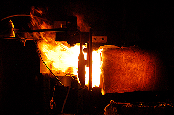
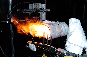
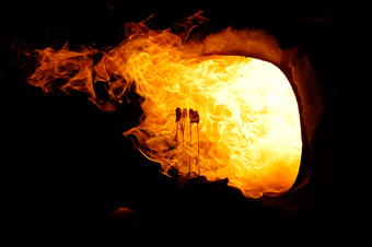
The NexGen Burner was developed to test the fire penetration resistance of thermal acoustic insulation. It was mainly created to replace the Park DPL 3400 burner, which is no longer in production. It can be modified to suit the requirements for fire tests on powerplant components. The NexGen burner is suitable for fire tests on powerplant components as it generates a “sooting” flame, which is representative of real-life fire situations.
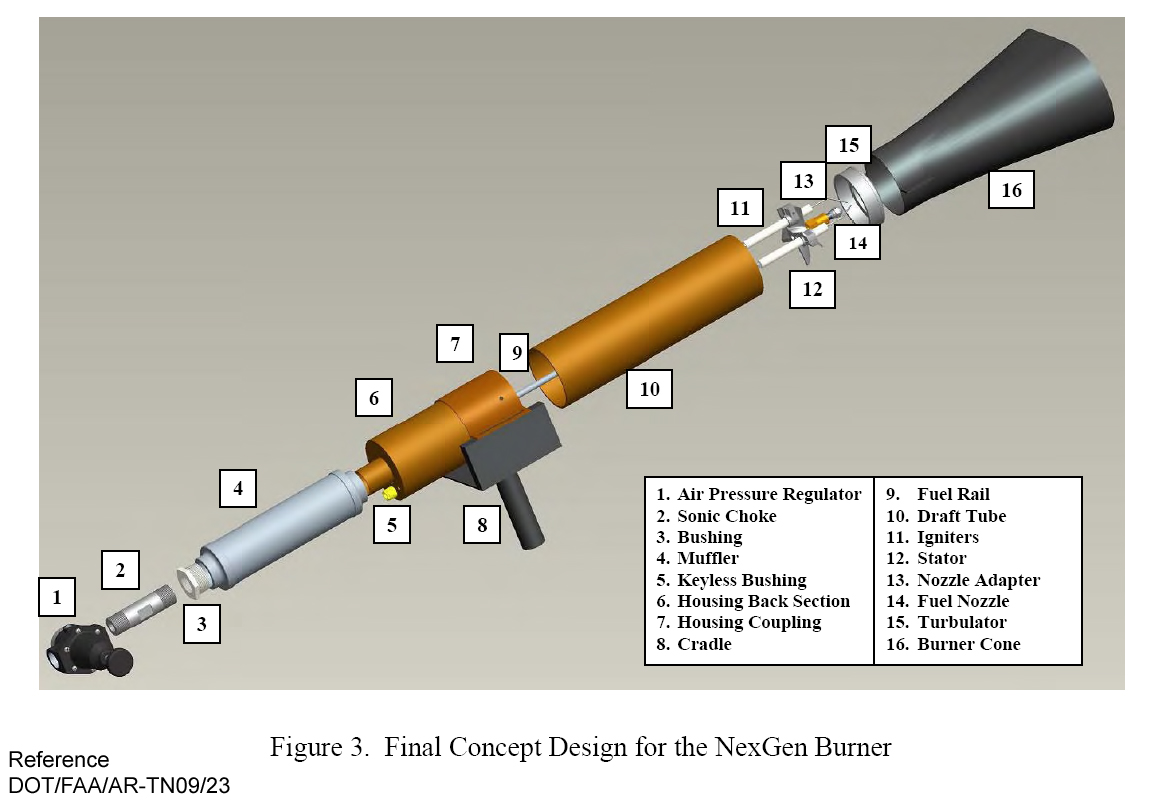
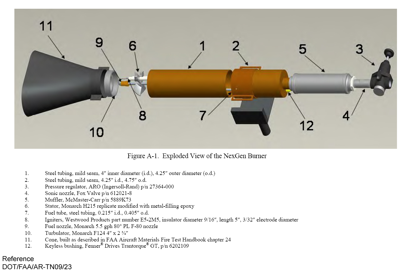
Burner Details and Construction
The burner is constructed of several commonly available components, which are described in detail in (reference TN09-23). The burner housing is a 4 inch ID tube. Swirl is added to the flow by means of a stator and a turbulator. A Monarch H215 stator used to generate swirl in the airflow and is located 4 inch upstream of the fuel nozzle. A Monarch F-124, 4 inch by 2 3/4 inch turbulator is attached to the end of the housing, and adds an opposite-sense swirl to the airflow, thus generating counter swirl.
Fuel is supplied through a 1/8 inch steel pipe. The fuel nozzle used is a Monarch F-80 5.5 gallon per hour (GPH), 80° PL hollow-cone fuel nozzle. It is attached to the fuel tube via a standard 1/4 inch adapter. Ignition is achieved through two ceramic insulated electrodes which are mounted on the stator. A High voltage transformer is used to create a spark between the two electrodes to provide an ignition source.
Burner Modifications
The NexGen Burner was initially designed for fire tests on acoustic insulation, the required flame properties for which are a temperature of 1900 ± 100°F with a heat flux of 16 ± 0.8 BTU/(ft2-s). For fire tests on power plant components, the requirements are a temperature of 2000 ± 150°F and a minimum heat flux of 9.3 BTU/(ft2-s). Thus we need a higher temperature flame, but with significantly lower heat flux. In order to achieve this, certain modifications were made to the burner.
In order to reduce the heat flux, it is necessary to lower the heat capacity of the flame, i.e. the fuel flow rate. In order to obtain sufficient fuel atomization at the lower flow rate, the fuel nozzle was replaced by a Monarch 2.25 GPH 80° PLP nozzle. Four tabs were installed on the turbulator at the 12, 3, 6 and 9 o’clock positions, to ensure suitable fuel flow distribution. The tabs were constructed of 1/16 inch thick stainless steel sheet and were 3/4 inch × 1 inch in size (reference AC 20-104). Additionally, the burner cone was insulated with a 1/2 inch thick ceramic blanket to minimize heat loss through the cone surface.
Temperature Calibration
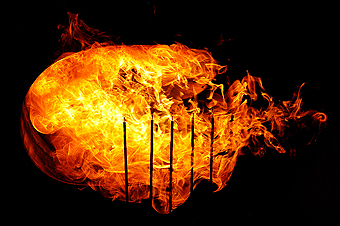
A detailed temperature map of the NexGen burner at the test plane (4 inch from exit) was obtained by traversing a 7-thermocouple rake within the test plane. The results of the temperature map are shown in Fig. A region with temperatures suitable for powerplant fire tests was obtained between a height of 1 inch – 3 inch above the centerline of the nozzle. Based on this, it was recommended to have the test target 1 to 1.5 inches above the centerline of the burner.
Heat Flux Calibration
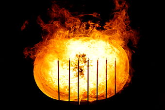
In addition to temperature calibration, a heat flux map of the burner was also obtained by using a 1-D traverse to change the height of the heat flux tube with respect to the burner nozzle. The heat flux measured was of the order of 13 BTU/(ft2-s), which is about 40% higher than the minimum required heat flux. High heat flux is generated due to the high air/fuel flow rates required to achieve the desired flame temperature at the test plane.
Summary
The NexGen burner is an oil burner that was initially designed to test fire penetration for acoustic insulation, and is currently being adapted for fire tests on powerplant components. The flame generated by the NexGen burner is “sooting,” therefore closer to real-life fire situations. With some modifications, it was possible to obtain the “2000°F minimum average” requirement for powerplant tests, though the heat flux was 40% larger than the minimum required heat flux. |