Reference ISO 2685
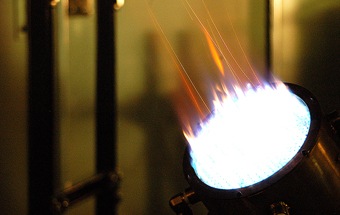
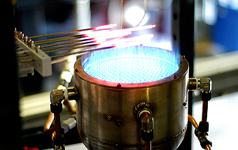
Plenum: A mixture of propane and air are introduced through the base of the burner before reaching the flame head.
Burner Head: The burner head must act as a flame stabilizer, and should also prevent flashback into the plenum chamber containing the combustible mixture. In order to achieve this, the burner head is made up of two plates with a 1” separation between then. 1/8” diameter copper tubes with a bore of 0.07” act as fuel nozzles and connect the plenum to the flame surface, which is the upper part of the flame surface. There are 373 copper tubes mounted on a grid, with a 0.3” spacing between them. 4 cooling holes on the exterior of the burner provide additional cooling air into the space between the two plates. The cooling air exits the burner through 332 holes in the top plate, 0.1015” in diameter, each hole located in the center of a square formed by 4 adjacent copper tubes. The cooling air cools down the copper tubes, thus preventing flashback. The cooling air also provides additional air to the flame, thus helping to maintain the burner temperature at the level required for the test.
Detailed Temperature Calibration
A detailed temperature map was obtained by traversing a single thermocouple across the measurement plane of the ISO burner. For the ISO burner, measurements need to be conducted at a distance of 3 in. (75 mm) from the burner nozzle. The temperature measurements were conducted over a 3 in × 3 in. square block centered at the center of the measurement plane, with data collected at 0.5 in. intervals (49 locations). The temperature distribution obtained was very uniform, with an average temperature of 2046°F with a standard deviation of 30°F.
Calibration Setup for the Fire Test
For the test, a 7-thermocouple rake was used to monitor the flame temperature. The temperatures were recorded by a National Instruments Data Acquisition System (DAQ) every second for a period of 3 minutes. The requirement for the calibration is that the TCs should be located at least 1 in. apart from each other and that the calibration area should cover at least 25% of the burner area. To achieve this, the TCs were arranged in a 4 in. × 4 in. grid as shown. This ensures temperature check over an area of at least a 4 in. diameter circle, which amounts to 44.4% of the burner area. The actual coordinates of the 7 TCs in the measurement plane are (-2, 0), (-1, 1), (-0.5, 2), (0, 0), (0.5, -2), (1, 1), (2, 0). The temperature traces for pre- and post-test calibrations for an engineering test are shown. For both calibrations the temperatures are seen to be stable and uniform difference between the highest and lowest temperatures being less than 100 F.
Heat Flux Calibration
The requirement for the flame is a minimum heat flux rate of 106 kW/m2 (9.3 BTU/ft2). For calibration, the heat flux needs to be measured over a period of 3 minutes. The pre- and post-test heat flux calibrations conducted during an engineering test are shown.
Summary
The ISO burner is a viable substitute for the Park Oil burner which is no longer in production. It is easy to operate and control and provides a stable, non-sooting 2000°F flame with the required heat flux intensity. It is applicable for fire-testing of small-to-medium size powerplant parts. |
|